Introduction
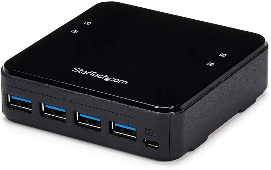
As a part of my work from home setup, I put together a “poor man’s KVM”. I have 3 computers, 2 monitors, and 1 mouse/keyboard. The first and second computers can share a monitor, and the third gets its own. For switching the display between the 2 computers I just use a simple DisplayPort Switch. To share the keyboard/mouse between the 3 computers, I use a 4 way USB switch.

Problem
This setup works reasonably well. Since the DisplayPort connection physically switches between devices, I don’t have to worry about latency at higher framerates. The problem is how you switch the USB Switch. They give you a little button on a 6 ft cable and you press that to move to the next computer. You have to think about which computer you are on and press it the correct number of times. If you want to go back to the previous computer, it results in 3 button presses. Do that enough times and it gets old really quick.
Solution
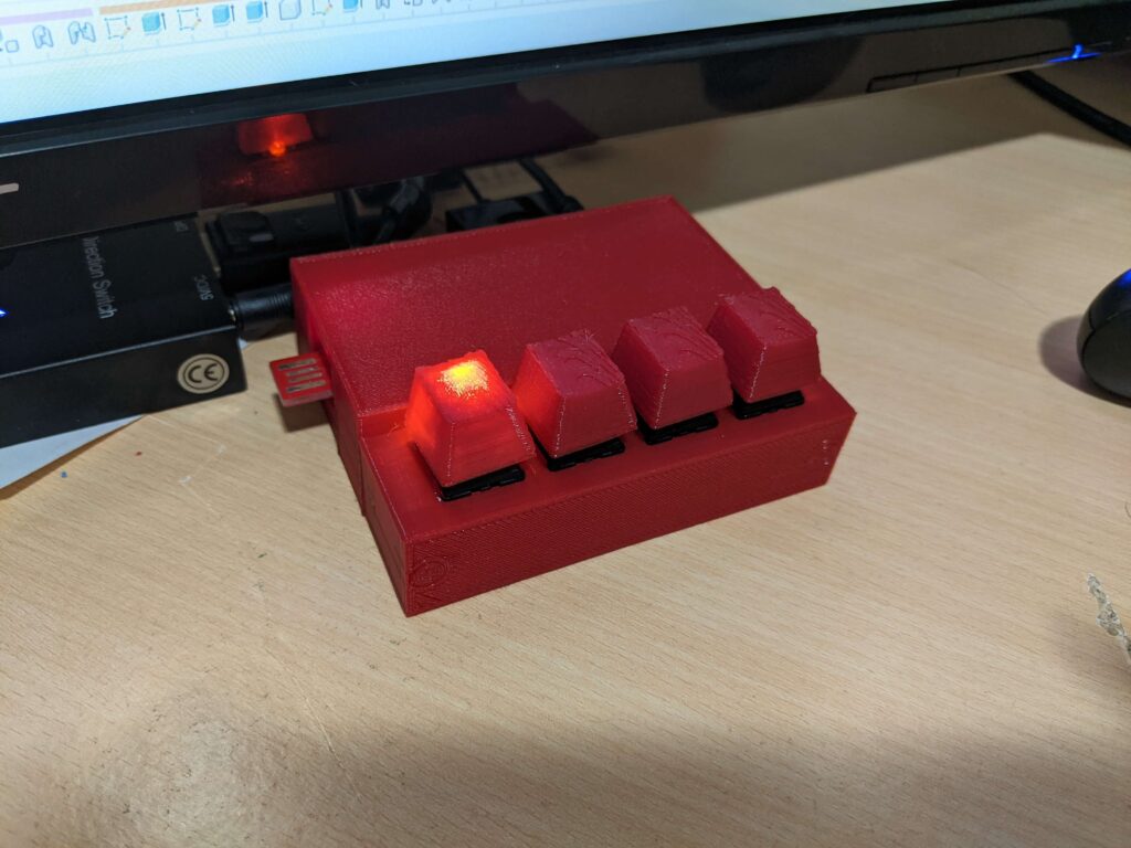
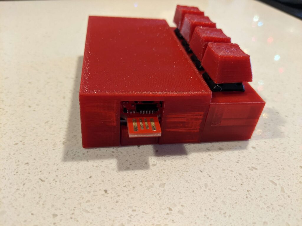
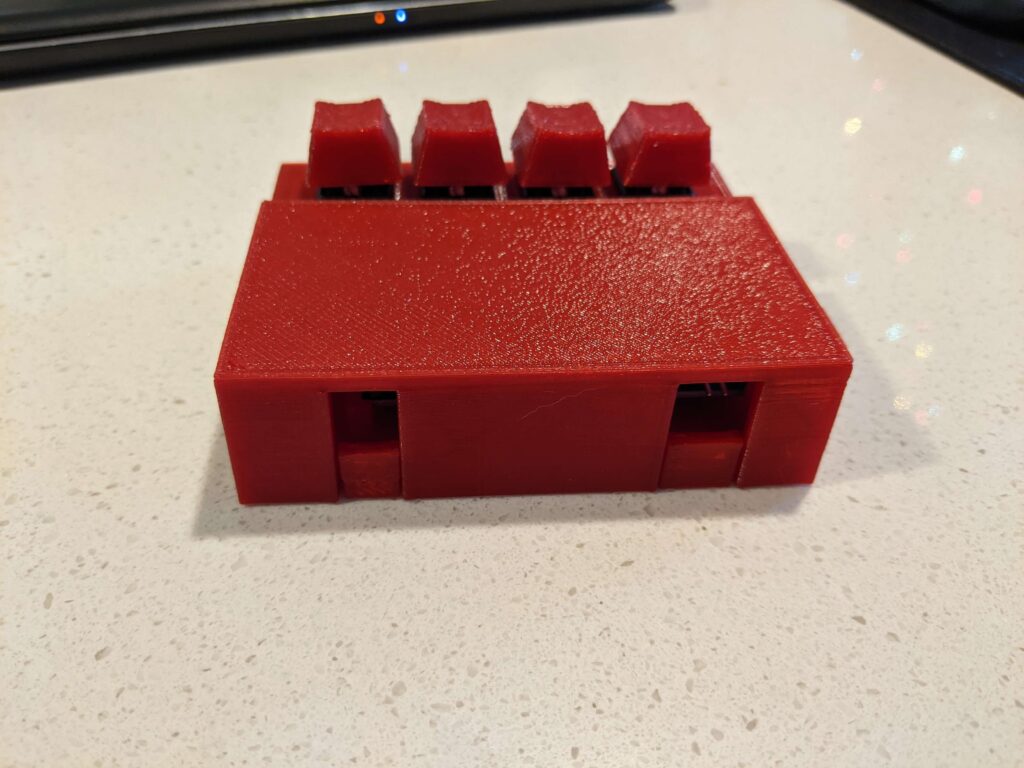
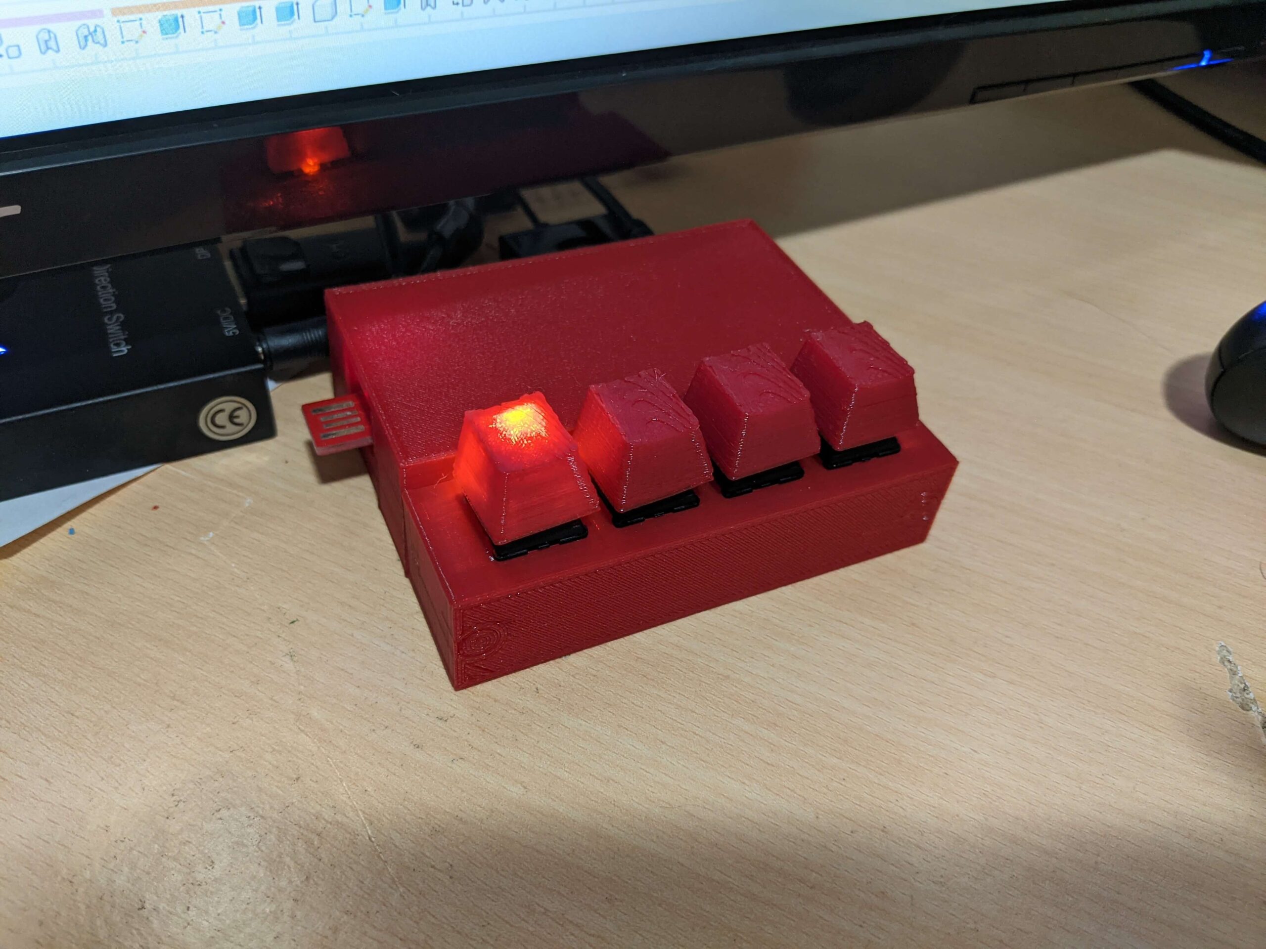
I built my own switch box! Each physical key on it maps to a specific computer. An LED backlight on the key indicates the currently active computer.
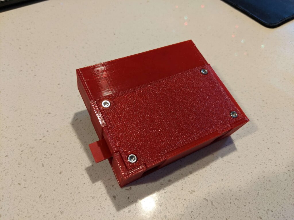
Bonus Feature
What happens if the switch box boots up but the first computer isn’t the active one? If you press all 4 buttons together, it switches into a “manual” mode. Just press the first button until computer #1 is active, then press button 4 to go back to regular mode.
Make your own
- Code is available on my GitHub
- STL files for the shell on Thingiverse
- Parts (estimated, I didn’t create a log of parts while building):
- 1x 3×7 CM PCB – I used this one
- 4x cherry keyboard switches
- 1x SparkFun RedStick (retired, so maybe replace with a small form factor Arduino?) RedStick for reference
- 1x TRRS 3.5mm Jack Breakout
- 1x 2.5mm Male to 3.5 Male 4 Conductor Audio Cable
- 6x M3x8 Bolts
- 2x M3 heat-set inserts (to hold the front key box to the main shell. If you modify the STL to shrink the hole size that would probably be fine. I just like heat-set inserts) example
Discussion
First I needed to determine how the button worked. It is just a snap-together part, so disassembly is really easy.
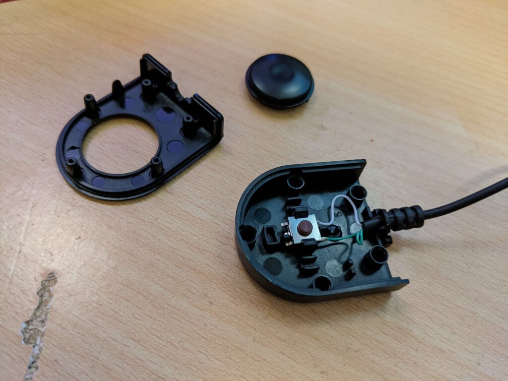
Looks like it’s just 2 wires. A quick check with a multimeter in continuity mode shows that the tip and the ring of the TRRS connector are connected when you push the button. Using the multimeter to check when plugged into the actual USB Switch Hub shows that the tip is held at 5V and the ring is ground. Easy enough, we just need to hold the tip HIGH until we want to “click” it, during which we will briefly bring it LOW.
The keyboard keys are easy as well. I just set the Arduino’s pins to INPUT_PULLUP to pull the pins high via an internal resistor. When you press the keyboard key it will connect the pin to ground, bringing it LOW.
Since I’ll only have at most 2 LEDs on at a time (manual mode), I’m going to cheat and use a single current limiting resistor for all 4 LEDs.
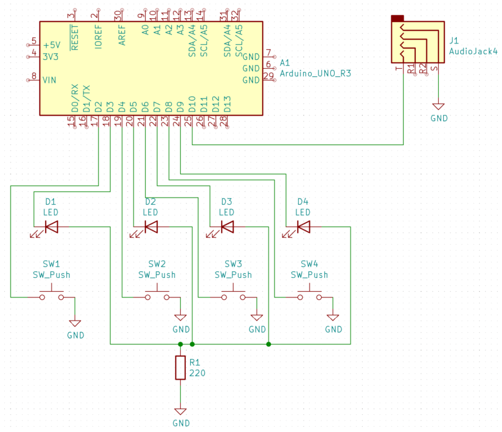
With the hardware designed, I soldered it together to start playing with it. I did run into a snag here (this is why you make an electrical schematic). I originally used the 220-ohm resistor as the ground for the buttons. This created an issue where if an LED was on, the buttons would never be able to go LOW when pressed (held HIGH by LED). Originally I made a mess in my code which turned off the LEDs to sample the button, then turned them back on. I figured this was just too nasty to allow, so I went ahead and re-soldered the board to make the buttons actually used ground.
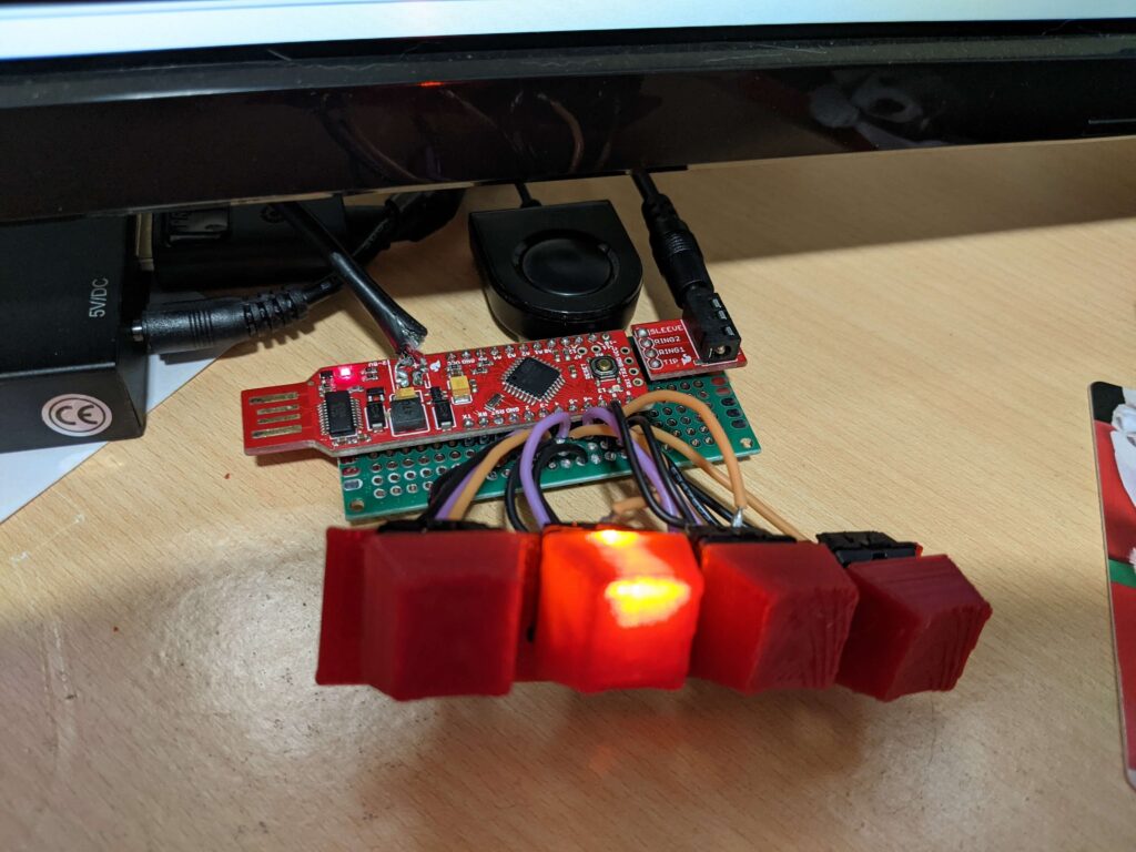
The code is pretty simple. It just tracks which is the currently active computer, checks for button presses, and if a button is pressed it sends the appropriate number of pulses to switch to that computer.
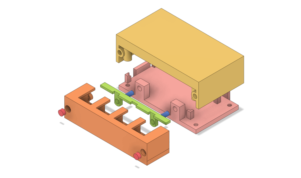
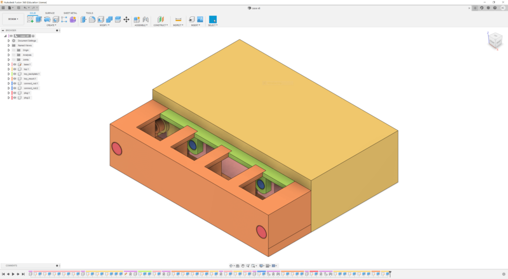
Once the prototype was working, I just modeled up a case in Fusion 360 and printed it on my 3d printer. I ran into issues printing the thin columns of the key mount (shown in orange below). They were very thin with nothing surrounding them. To fix it I added some ribs connecting the top to bottom.
Lessons Learned
- No matter how simple the wiring will be, make an electrical schematic. It will let you better check your work and find hardware bugs much earlier.
- Tall, thin walls need support. Even a thin rib is much better than nothing.
Leave a Reply