Author: anichno

  • D&D Tabletop Tracking System – Part 2

    D&D Tabletop Tracking System – Part 2

    This is part 2 of my D&D Tabletop Tracking System project. If you haven’t yet, you might want to read part 1 to catch up!.

    The following post will be written with the project state as of November 2024.

    Demo First!

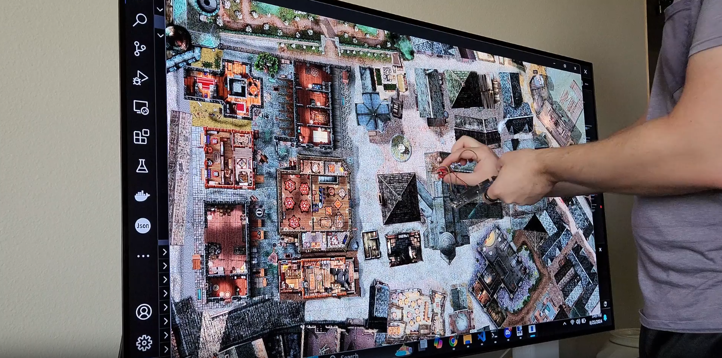
    Shown in this demo is a program on the target microcontroller (an nRF52) with a light sensor (not quite the one I intend to use, but similar enough) running on battery power which can locate itself on the map. If you watch carefully, you can see the screen flash a sort of grid which is visible as patches of differing brightness levels. For demonstration purposes, the flashing is much slower than the goal, which is to flash on each frame (~33ms per flash). Once the light sensor receives a location by watching for the flashes, a green box is drawn around it to show where the system thinks it is.

    Introduction

    For this post, I wanted to discuss the design constraints I’ve been working under, the hardware so far, some certification stuff that I had not considered, and an unexpected hard problem. I’ve received a lot of suggestions while working on this project which has been extremely helpful, but since others don’t know the reason for some of my decisions I’ve had to reject some input. My hope is that communicating what design constraints I’ve been using and why will help get everyone on the same page.

    Since my last update, I have continued to work on this project and am even close to sending it out for manufacturing! Hopefully, I will soon get physical copies with all the sensors and microcontrollers integrated into an approximately 1-inch diameter printed circuit board.

    Design Constraints

    While working on this, I have been using the following constraints to guide my solution:

    1. Minimal External Hardware
    2. Size
    3. Power
    4. Cost

    I treat these as goal/guiding principles, so if there is a reason to violate/adjust them, that is ok. At the end of the day, this is a “for fun” project, but I’ve at least tried to keep a bit of structure around it.

    Minimal External Hardware

    For this project, I need to minimize the amount of “stuff” required to make this work. At a minimum, I know I already need the following:

    • A TV: You were already trying to use it for a dynamic map.
    • A Computer: Needed to run the virtual tabletop system (VTT)
    • Minis: Physical tokens to put on the map

    This means I want to avoid if possible the following:

    • External Cameras: These require some sort of mounting solution and power supply, and can be pricy.
    • Frames: This is anything that attaches to the TV. These take up space and may require some form of careful alignment.
    • Bridging Devices: This would be any device that sits to the side which acts as a way for any remote devices to connect to the computer running the VTT.

    Size

    This has been one of the more difficult constraints and also is a heavy driver of the following “Power” constraint. Miniature bases are approximately 1 inch in diameter, and standard grid sizes are 1 inch. Since we are working with a map on a TV screen, technically we can expand the grid (for example: make it a 2-inch grid). However, that causes problems like significantly reducing the amount of map which can be displayed at any given time. I also think bases that are much bigger than the size of the mini would look sloppy and from laying out the components I believe I can fit everything with that 1-inch diameter.

    Power

    Running any cable to the mini bases would violate the first constraint (Minimal External Hardware). Therefore, any power needed by the base has to come from a battery. Unless I want the base to be really tall (multiple inches), the only viable power source is coin cell batteries.

    Coin cells have limited capacity, but even more limiting is how much current they can source at any moment in time. In general, a CR2032 (the one that looks like a quarter) can only source a continuous current of 15 milliamps. For reference, many small LED lights consume roughly that amount. This means we have to power all our sensors and our microcontroller on that limited amount of power! Since we aren’t running cables back to the computer, whatever we use for wireless communication also needs to fit within this power budget.

    Cost

    While I don’t yet know if I will try to commercialize this, I wanted to try to design it in case I do. Making 1 or 2 of a thing is a lot different than making thousands of a thing and they have very different cost structures. If my bill of materials gets too expensive, then after I add in manufacturing costs and profit margin, it could end up too expensive and no one would be willing to buy it.

    This means I probably can’t pick the biggest and baddest microcontroller, the best on the market inertial measurement unit, or the fanciest high-resolution camera. Instead, I need to pick “good enough” components that satisfy my requirements without providing excess capacity that doesn’t add value.

    Engineering is all about resource allocation. Anyone can build a bridge, but only an engineer can build one that barely stands.

    Hardware So Far

    I have prototyped out some hardware which is currently able to implement what I called the “Duck Hunt” solution from part 1. It is all built into a base that the mini would sit on.
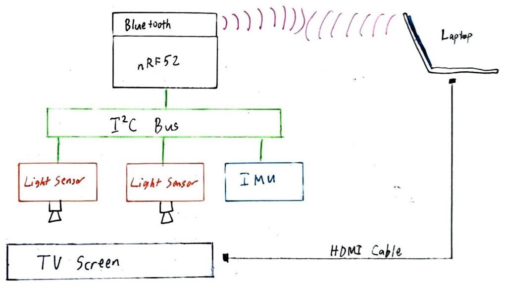
    The major components are:

    • nRF52: This is the microcontroller that is responsible for reading the sensors and communicating with the computer via Bluetooth
    • OPT4001: Two of these act as light sensors that watch the screen for shifts in brightness. They are not sensitive to any particular wavelength (they read general brightness, not specific colors). Why two? The idea is by putting some sort of gradient on the screen I can use the different readings between the sensors to determine rotation.
    • LSM6DSO: A six-axis inertial measurement unit (IMU). It includes a 3-axis accelerometer and a 3-axis gyroscope. This sensor is intended to detect pickup and placement of the mini base, as well as approximate its location in space while it is being held/moved (more on this below).

    This current solution aligns with the above constraints

    • Minimal External Hardware: The only additional hardware is the base which attaches to the bottom of the mini.
    • Size: Layouts of the selected components fit within a 1-inch diameter. The coin cell (CR2032) plus its holder are just under the 1-inch diameter. With a plastic case around the circuit board and battery, we might miss the 1-inch diameter by a few millimeters.
    • Power: Powered from a CR2032 coin cell battery. With how low-powered the nRF52 is, I think it may be able to sustain weeks of active use (and months of standby time).
    • Cost: The current bill of materials is roughly $10 for each when building in batches of 100.

    Certifications

    Something I didn’t think about needing for this project is a wireless certification. It makes sense though, we are emitting radio energy and regulatory bodies such as the FCC have opinions on that. This is only an issue if I intend to sell these, not if I was only making these for myself.

    Certification is expensive! Since we are using a radio, this device would be classified as an “intentional radiator”. I’ve seen estimates anywhere in the range of $10k to $100k to get these kinds of devices certified, which would be backbreaking for a project of this small scale. There are some carve-outs for small-scale production, which allows you to see if there is market fit before paying for a full certification, but overall this is a big hassle and expense.

    There is however a remedy for this. If I instead use a pre-certified radio “module”, then I only need to get certified as an “unintentional radiator”, which is much cheaper, in the range of $1-2k. For this project, I’m using an nRF52 which has Bluetooth radio functionality built in. If I buy a precertified module I’ll pay a little more per unit, but not have to design my own antenna or go through the much more stringent and much more expensive intentional radiator certification process.

    These modules can be pretty small, so this is definitely the right design decision.

    Unforseen “Hard” Problems

    With the “duck hunt” approach, every time you move or place the mini base you will trigger a location update routine. This is where we get the screen flashing shown in the demo above. While the intensity of the flashes can hopefully be minimized, it will still likely cause some amount of flicker. That update will happen on every move, regardless of how small or simple it is.

    To solve this, I figured why not include an inertial measurement unit (IMU). I already needed some way to detect that a mini base had been moved to trigger a location update and an IMU is a great fit for that task. If an IMU already measures acceleration and rotation, how hard could it be to have it use that data to estimate the new position of the mini base? Then I could do a “guess and check” where I flash only under the mini (to see if the estimate was correct). If the estimate is incorrect then worst case I fall back to flashing the whole screen. Easy right?

    WRONG! After playing with the IMU and some test code, I began to suspect that I might have stumbled into a legitimately hard problem. The issue I kept seeing, regardless of how I tried to correct for it, was that my IMU would build up positional error rapidly. Within seconds it would think it was somehow meters away, even if it was physically not moving.

    The following video does a really good job of explaining the problem I stumbled into (23ish minutes in, the section on double integration):

    If you don’t want to watch the above video, here is a quick summary of the problem. An accelerometer measures acceleration, not position. To get the position, you:

    1. Take the acceleration and multiply it by the difference in time since your last measurement, then add that to your previous velocity, giving you your current velocity.
    2. Take your current velocity and multiply by the time difference again, which will give the distance you have moved since your last measurement. Adding that to your previous position gives you your current position.

    At every step, any error you have gets magnified. Additionally, the accelerometer measures acceleration, which includes acceleration due to gravity. If you have any error in removing the gravity vector from your measurements, your position estimates will be wildly off.

    An Opportunity for a Rabbit Hole

    Not being able to interpret the IMU data to determine our position directly is a big bummer. If this was straight impossible, we could just walk away. However, I found a bunch of fairly recent research discussing using machine learning (ML) to interpret the IMU and output corrected position information.

    Here is a link dump of several examples of using ML to interpret and correct IMU data:

    Approaches like this are fascinating, but present a new problem: several require some form of ML models, which take a lot of computing and memory to run. Microcontrollers are resource-constrained: they have limited processing power, memory, and even storage. So is it even possible to use these approaches? Yes! There is something called TinyML/Tensorflow lite for microcontrollers!

    As long as your ML model isn’t too complex, it is possible to run it on the microcontroller directly. Here are some books focused on TinyML:

    The siren call is strong, but I must remember that position estimation from an IMU is not required for a minimally viable product, so for now I’m going to let this go.

    Conclusion

    Congrats on reading this far! I hope you enjoyed this update (and if you did, consider sharing it with a friend!). Be sure to keep an eye out for part 3 (which should be the current state of the project). If you are interested in the code I’ve been generating while playing with this, check it out at: https://github.com/anichno/tabletop-mini-tracker.

  • Semantic Search for Home Organization

    Semantic Search for Home Organization

    Introduction

    I don’t know about you, but I have a lot of “stuff” just sitting in bins, especially around my project space. This stuff is largely a collection of tools and parts for projects I’ve done in the past. This even includes parts reclaimed from abandoned/incomplete projects, as well as the tools I may have purchased to help myself work on them. This stuff is potentially useful though and expensive enough that I’m not willing to clean it all out. I’ve also found that having parts accessible helps reduce “friction” when working on something new. If I already have the parts, its much easier to play with a new idea or concept. Amazon 2-day shipping is fast, but it’s not “open a drawer or box” fast.

    Problem Statement

    I forgot I had these!

    With all this stuff lying around, it’s hard to know what I have. Even worse, I might know I have a particular part or tool, but no idea where it actually is! Wouldn’t it be cool if I had a way to search for the stuff I have, as well as have that system tell me where it is?

    Playing with a solution

    To begin, I started just creating notes in Obsidian. For each item, I took a photo and then linked it to the note. Then I gave it a name and a text description. That way, I could “search” on keywords and get a picture to compare against what I thought I was looking for. For organization, I could sort the notes into folders (example: Project Room -> Closet -> Bin 1 -> test_probe.md).

    As a basic approach, this actually worked, but there is a lot of overhead. The process currently looks like this:

    1. Take a picture of the item.
    2. Create a note in the appropriate folder structure.
    3. Give the item a name.
    4. Give the item a description.
    5. Link photo to item.

    Other than the problem of me just being plain lazy and the above being a lot of work, I have another problem: What if when I search, I can’t come up with the correct text?

    Semantic search to the rescue!

    Instead of searching based on literal text (lexical search), what if we could instead search on concepts and meaning? This is where semantic search comes in. Semantic search attempts to find results by considering how semantically similar (how close in meaning) your query is to all the possible results. Computerphile has a really good explainer of the core of this, vector embeddings:

    In short, by looking at how words are used in lots of text examples, we can model how similar they are to other words. In practice, these words (or even phrases) can be placed into a highly dimensional space, where each dimension can represent things like “how catlike vs doglike”, “how fancy”, or “how male or female” (these are examples, but a machine learning system “learns” how it wants to use its dimensions based on input data and its evaluation function, and are likely not as simple as my examples).

    To use this in search, it’s really “easy”, all you need to do is:

    • Use an embedding model to encode the names and descriptions into a highly dimensional space
    • Store that embedding in a vector database (in practice, an embedding is just a series of floating point numbers)
    • Generate an embedding for any query we would like to do
    • Search the vector database for the nearest neighbors of that query

    Standing on the shoulders of giants

    Luckily, tools for the above exist. Here are the ones I used:

    • FastEmbed
      • For embeddings, I used FastEmbed. Specifically, I used this implementation since it is a Rust-based implementation and I wrote my web app in Rust. This library can be used to generate the necessary embeddings for my descriptions as well as my queries.
    • Mxbai-embed-large-v1
      • I picked this model somewhat arbitrarily. It seems to be ranked well on embedding leaderboards and I had plenty of RAM to run it locally (approx 1.25 GB).
    • Sqlite-vec
      • This provides a Sqlite extension that can do the necessary vector searches. What is nice is that Sqlite gets built into your application, so you don’t need to manage a whole separate database application. Instead, you have Sqlite as a library and a single file which is the state of the database.

    New (old) problem, I’m lazy

    Semantic search is cool and all, but do I really have to write all those names and descriptions? The above approach to data ingest is going to be way too burdensome, involving lots of time and decision-making per item. However, you know who will happily give me names and descriptions for money? OpenAI! (or any other large language model (LLM) provider with models which can process images)

    Given an image as context, the LLM query looks like:

    • System Prompt: “You are a helpful item identifier and described. You always respond in valid JSON.”
    • “Please give a short name for this object.”
    • “Please give a full description of what you see in this image. Do not mention the background or any human hands.” (If I was holding something like a USB cable, the LLMs really liked to tell me about my hands)

    Pro tip: You can constrain output to valid JSON, just provide a JSON schema and instruction in the system prompt (https://platform.openai.com/docs/guides/structured-outputs)

    Inputting new items now looks like this:

    • User: Take pictures of items against a simple background.
    • User: Zip them all up and tell the inventory system which container they go to.
    • Program: Let OpenAI give each item a name and description.
    • Program: Embeddings are generated from names and descriptions, then stored in the database.

    Then we can query the database based on semantic meaning instead of keywords.

    Oh no, Anthony got really obsessed and made a web app

    The following videos demonstrate some of the functionality and what this app looks like at the time of writing.

    First, we do a search for the term “programmer”. Note how you get results such as tools that help you program things. You also get stuff with the terms “developer” and “development” which are conceptually similar to “programmer.


    Next is an example of searching based on the concept of “something to put small things in”. The results include several small pouches which could be used to store small items.


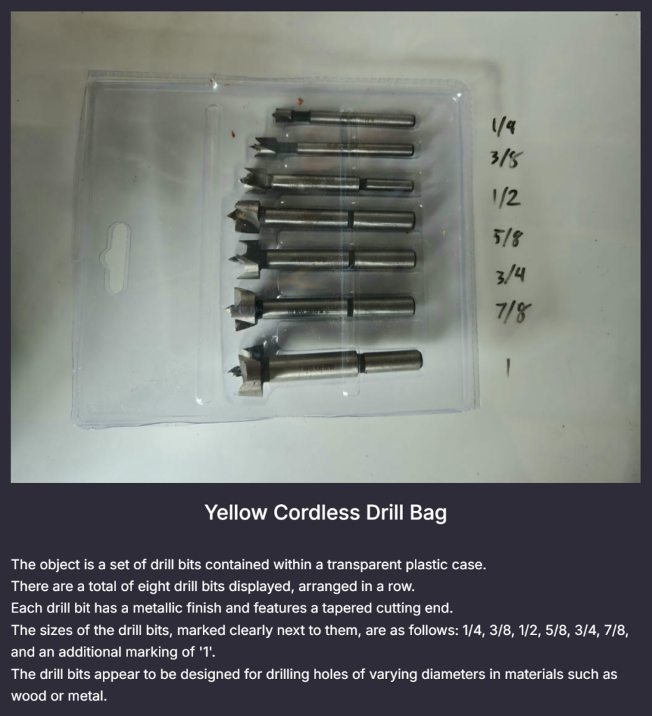
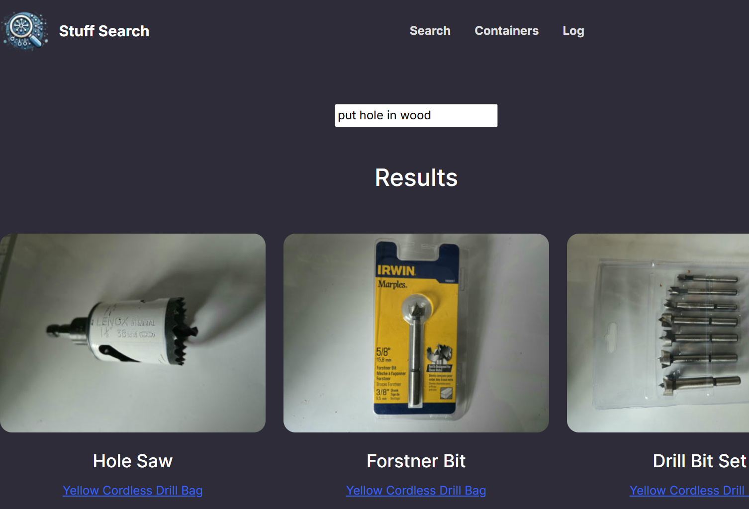
    For the last search demo, we search for “hole in wood”. As expected, we got multiple drill bits and wood screws. Note how the description for “Drill Bit Set” does not contain the words “wood” or “hole”.


    Because the LLM is doing its best to read all text it sees, we can make sure some makes it into the description by writing it off to the side on a whiteboard:

    Note how all the drill bit sizes made it into the description.

    Finally, I wanted to show the “containers” page. It lets you browse your containers and move items around via drag and drop.

    Web app tech stack

    As mentioned before, the database implementation is Sqlite-vec. The backend code uses Axum, which is a Rust web framework. CSS/styling is done with Bootstrap 5. HTML templating was provided by Minijinja.

    It’s been a few years since I’ve last made a web app and I was NOT excited to have to relearn a framework like Angular or VueJS. However, I decided to finally give HTMX a try and that was an absolutely lovely experience. I recommend giving their essays a read and the library a look. In short, you get extra HTML tags you can put on elements, which give them a lot more dynamic functionality. Using it I had a very responsive, modern-feeling web app with very little effort.

    I also wanted to shout out Bootstrap Studio, which provides a really nice WYSIWYG editor for web pages. I’m not very familiar with the ins and outs of Bootstrap and CSS in general, so being able to play with the look and feel in the editor was very helpful. While my app isn’t the most impressive visually, I think it helped me get to something functional pretty quickly.

    Problems and Pitfalls

    Even with the automation, it is still a non-zero amount of work to go through and inventory my stuff. I’m hoping it’s a low enough effort though that I will continue to use and update the system. Because there is a level of friction with organizing stuff managed by this app, I figure this is more useful when used as an “archival” solution. If you are taking items in and out frequently, you should probably consider a different way of doing this.

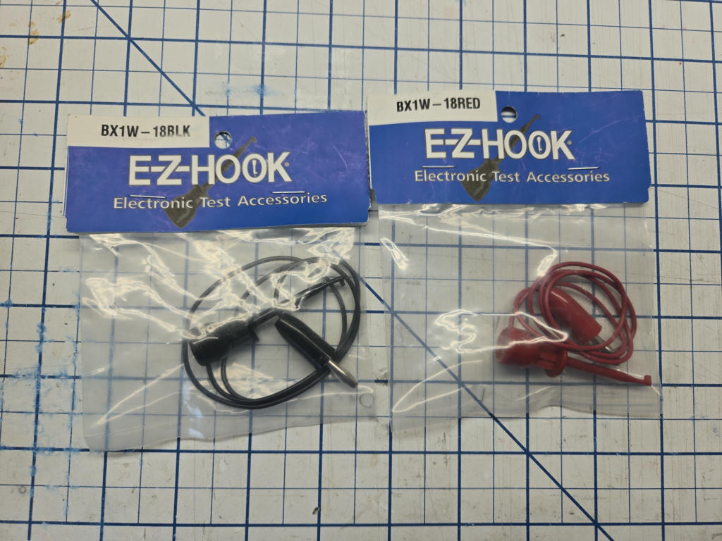
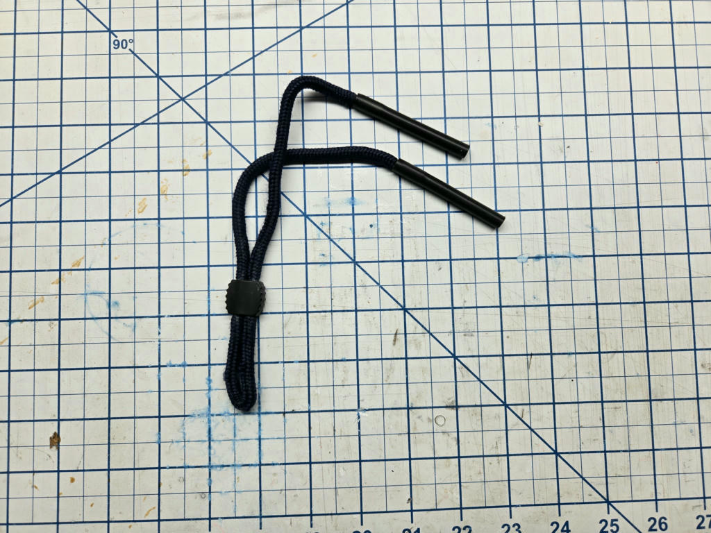
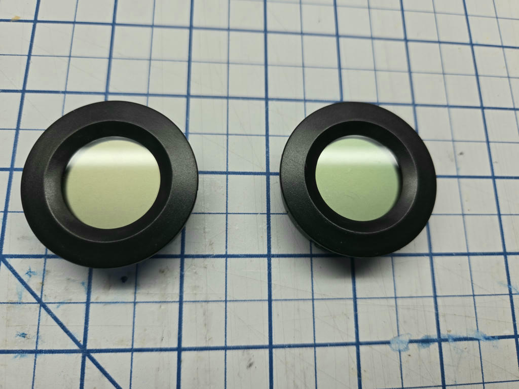
    While the AI approach is super useful for data entry, it faces limitations as well. The most obvious problem is it doesn’t always know what it is looking at. I find this fair; when given no context and handed the following, would you be able to identify them?

    While fair that the system fails to identify certain items, it also fails to tell me it doesn’t know what it’s looking at (maybe this could be fixed with prompt engineering, but this is a general LLM issue). This means there is still a level of manual review necessary.

    Lastly, the age-old issue with inventory systems: how do I keep it up to date? As I pull things from boxes and put new things in, if I don’t keep updating the web app those items will get lost. It’s almost probably worse since if the bin is mostly in the inventory system, I won’t realize there are non-inventoried items in there. I think the best way to deal with this is just a periodic review (every year?) where I attest that the state of a container is still correct or make adjustments as necessary.

    Potential future work

    While I am trying to “lock” development on this project and just use it (otherwise projects have a bad tendency to just never be finished), there are a few improvements I would like to consider in the future.

    1. Clustering: Part of the value of generating vector embeddings for these items is they can be represented in a highly dimensional space where similar items would theoretically be close to one another. By identifying similar items, the system could propose new ways to sort stuff that puts similar items into the same or nearby containers.
    2. Reranking: In normal “retrieval augmented generation” (RAG) pipelines, reranking is a way to take a large number of initial results from the embedding search and “rerank” them such that only the most relevant ones are actually fed to the LLM that is processing your overall query. In this application, it could be useful to let the initial embedding query pull back a lot of candidate items and then pass it through a reranker to improve the quality of search results.
    3. Better chunking strategies: For the web app, I make several chunks of text and embed them separately. Better strategies may lead to better results. For reference, here is how I chunked at the time of writing:
      • Name only
      • Name + full description
      • Each line in the description (acting as a series of statements)
    4. Bring in an LLM: As currently implemented, an actual LLM is never used in the query process; it is only used for data ingest. There may be an advantage to doing the query, and then asking the LLM which is the best result. After validating that the result actually exists and wasn’t made up, we might have a powerful search tool. I do see an issue with this purely from a query time perspective. Search tools like this are expected to be fast, and the longer it takes to return the results the worse the experience is.
    5. Photo segmentation: Instead of taking one photo per item, you could take one photo of multiple items and then segment the photo into one photo per item. With a simple white background this could be pretty easy, but you’d have to handle the edge cases like where an item is really a collection of small parts that might be slightly separated from one another. If it was sufficiently accurate, this could reduce the overhead for getting large groups of items into the database.
    6. Integration with an existing inventory system: There are other inventory management systems that are much more fully fleshed out than this one. Building a plugin for another system such as Inventree might be a better long-term solution.

    Conclusion

    As of writing this, I’ve actually been using this for a few weeks with a few containers inventoried. Already it has been useful, with me using it to find which bin had some magnets I was looking for. The code is open source under an MIT license and can be found at: https://github.com/anichno/stuff-search. I’ve tried to include enough documentation there to get up and running, but just note that as of now the app will want a little over 1.25 GB to run (since it’s running that embedding model. Feel free to give it a try if you think it might be useful, otherwise it’s an example of how to do the things mentioned above.

    Thanks for making it this far! Feel free to leave a comment or share it with anyone you know who might find these kinds of projects interesting.

  • D&D Tabletop Tracking System – Part 1

    D&D Tabletop Tracking System – Part 1

    Series Introduction

    Welcome to my Dungeons and Dragons (D&D) tabletop tracking system project. This has been a complex project I’ve been working on and off for roughly two years. Since I have done presentations in the past, but never written any posts about it, I’ve decided to write these posts as if they had been written when I presented them. Therefore, while I have made many updates and progress over time, these posts will be written with only the knowledge I had then. Hopefully, this will allow you as the reader to follow along as I worked my way through various problems and solutions.

    The following post will be written with the project state as of August 2024.

    Problem Overview and Background

    For years I saved a large TV with the intent of building some sort of gaming table. The TV was intended to allow me to do things like run D&D games with dynamic maps and backgrounds. However, I am not a good/competent woodworker and this project never made much progress.

    Later, I happened upon a video of someone just putting their TV on an existing table. That is MUCH easier to manage than building a whole table! Instead, at most, I can make myself a nice box for the TV, potentially with a screen protector of some sort. I still haven’t built a box for my TV, but I have run a game where we just put the TV itself on the table.

    Instead of building a box for the TV and calling it a day, this spawned the huge project that will be covered by this and future parts. When playing with the dynamic maps using a virtual tabletop system (VTT) called Foundry, I found it super cool that you could have stuff like fog of war and limited fields of view. With that, I could have a full map “technically” on the screen, but until my players explored those areas it would not yet be revealed. Then, as they moved around, they would be able to explore the map.

    This is really cool if you are fully virtual or remote, but if playing in person we now have a new issue: how do we tell the VTT where the players are? I don’t want players to have to use something like a mouse, I feel like that breaks immersion. For our in-person game, I let them move their minis around the TV and then I as the game master “dragged” their token in the VTT to the appropriate location on the map. This worked ok but did require overhead on my part. I also needed to enforce a “party token”, so that I wasn’t having to manage multiple people moving around all over the place.

    What if players could use their minis (because minis are cool) with the TV-based tabletop system, but the underlying VTT was able to self-update itself with the location of players’ minis? Welcome to my project for the past two years…

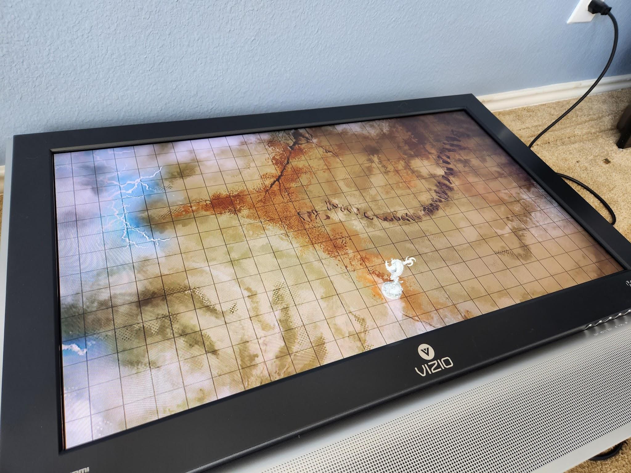
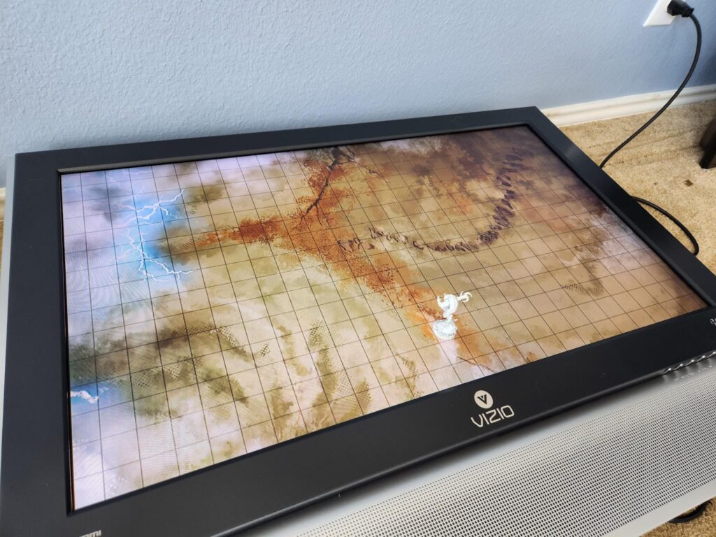
    Example of a mini on a TV. Wouldn’t it be cool if the TV somehow knew where it was?

    Prior Art

    I am not the first person to try to solve this problem. There are several really cool and creative solutions already out there, but of course, they weren’t good fits because of <insert arbitrary reason here>. Before getting into the approaches I’ve taken, I think it’s worthwhile to discuss what has come before, what is good about them, and what disadvantages I saw with them.

    Overhead IR Camera

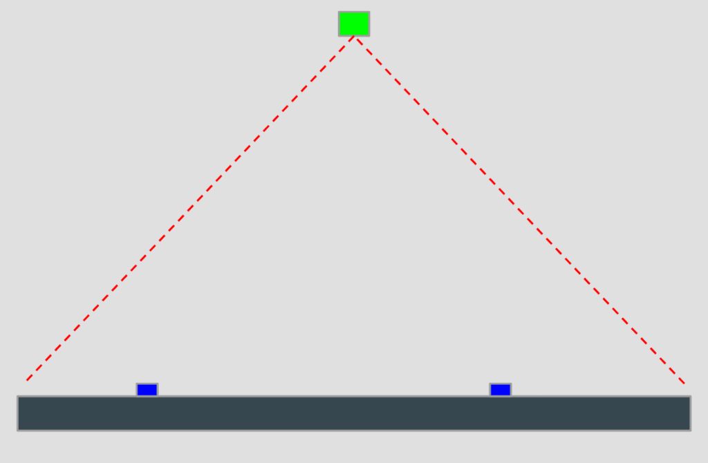
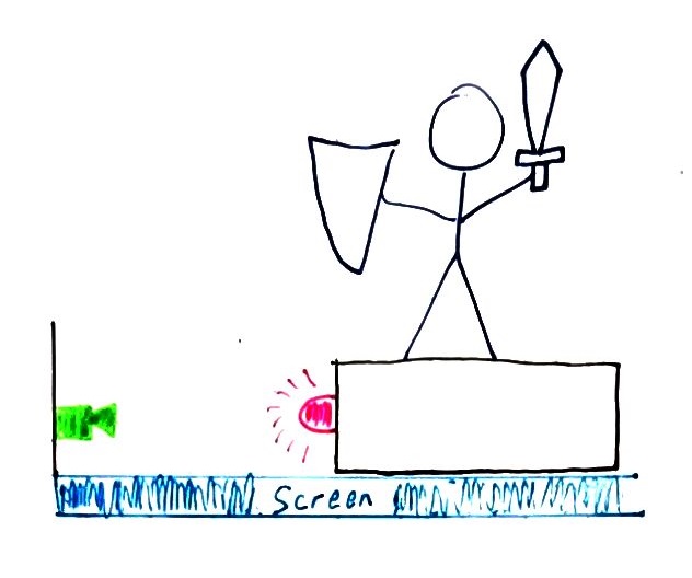
    This is probably the simplest and most effective technique to solve this problem. In general, it works like this (with an MS Paint quality visual aid).

    An infrared (IR) camera is placed somewhere above the surface, such as the ceiling. For each mini you wish to track, you put them on some sort of base which is capable of emitting an infrared code. Those codes are unique to each mini, so when the camera sees them, it can then know which mini is where on the physical screen. Using that positional data from the camera, you can update the VTT with the location of that person’s mini.

    Advantages

    • Simplicity: This system is relatively simple to implement. The mini bases do not need to be particularly smart, only enough to know a globally unique identifier and be able to emit that. Most cameras are sensitive to infrared light, so at worst you just need to remove the IR filter. The system does need to be calibrated, such that positions reported by the camera are calibrated against the physical location of the mini on the screen.
    • No Masking: Minis generally cannot “mask” each other, which will be shown to be a bigger issue in other approaches. Basically, if the minis are on the same plane of the screen, none can hide another from the view of the camera.
    • Unlimited mini tracking: You are only limited by the number of minis you can physically fit on the screen (which should far exceed the number you actually want to use). Each mini does not incur a noticeable increase in processing time for the system.

    Disadvantages

    • Requires a camera overhead: The camera must be mounted such that it can see the entire screen with its field of view. This can either be on some sort of boom or ceiling mounted.
    • Calibration on each setup: Every time the screen is set up, a calibration routine is needed to make sure the camera’s location is known relative to the screen for tracking.
    • Hands can mask minis: Hands and arms passing over the TV can hide minis from the view of the camera.

    Example

    This solution actually has a commercial product you can purchase and set up. It’s called “Material Plane” and can be found at: https://www.materialfoundry.nl/. It also has a corresponding Foundry VTT module to run it.

    If this whole project sounds really cool to you and you want to set it up right now, you should probably just go buy that one.

    IR Touch Frames

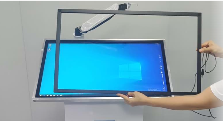
    This is another relatively simple approach. It is possible to make a standard TV “touch” capable by attaching an IR touch frame to it (examples: https://www.amazon.com/ir-touch-frame/s?k=ir+touch+frame). This approach works by using that touch information to track the lifting and placing of minis on the screen. As they are picked up, that point of “touch” is removed, and when placed a new “touch” point can be tracked.

    Advantages

    • Easy touch functionality: If your VTT map includes interactable objects such as doors, you can easily let players interact with them with a simple touch.
    • Inline with TV: Since the frame is just mounted to the front of the TV, you could easily build it into a nice frame with the TV.
    • Calibrate once: Once mounted and calibrated, the system should not go out of calibration.

    Disadvantages

    • Minis can mask each other: The frame works by projecting IR beams across the screen. This creates “dead zones” around things touching the screen since they create shadows.
    • Single mini tracking: This system works well if you only want to track one mini (such as a “party” token), but has issues with more than one mini. An example: you and your friend both pick up your minis, then place them again. With this, the system has no way of tracking which mini is which. The minis never had a way of identifying themselves, so instead at some point in the past we told the system that “touch point 1 is mini A”. Future tracking relies on assumptions of that point leaving and coming back as the same mini.

    Under Table Projector/Camera

    I thought this approach was quite clever. Sadly, after I saw it I failed to save the link to it to be able to source it later. Instead of using a standard TV screen, it used a projector hidden in a table under the screen, facing up. It could then project an image onto the screen from behind. Since the screen allowed light through (you could see the image after all), the researchers put QR codes on the bottom of objects they wanted to track. By putting a camera next to the projector, the system could look up at the screen and read the QR codes, giving it the ability to track the locations of objects on the screen.

    Advantages

    • No masking: If a mini was on the surface of the screen, it could be seen. No mini could “hide” another from the camera.
    • Simple software implementation: Make each QR code unique, then associate that code to a mini. Simply reading the camera and looking for the locations of each QR code gives you the location of the mini with which to update the VTT.
    • Unlimited mini tracking: You are only limited by the number of minis you can physically fit on the screen.

    Disadvantages

    • Specialized construction: While a cool idea, this requires building the entire physical system yourself. To my knowledge, there is no commercial product for sale that implements this.
    • Not portable: As described, this system is large enough that it would likely be placed and never moved.

    My First Approach

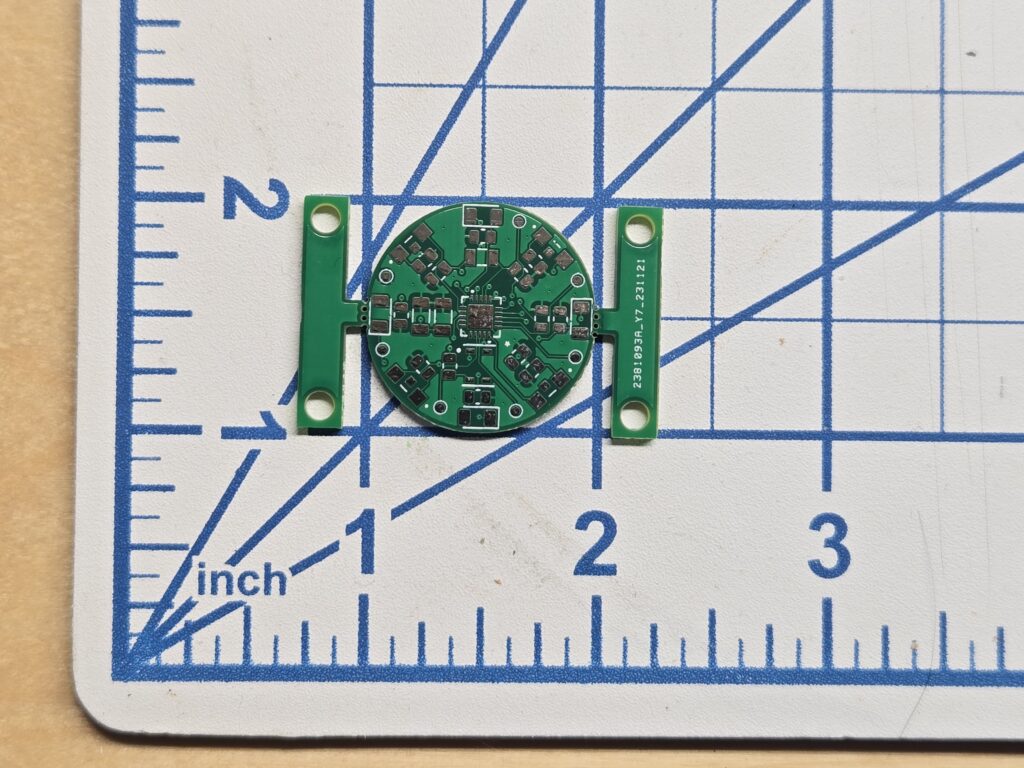
    I spent a lot of time on this first approach before ultimately abandoning it. I even got as far as having printed circuit boards (PCBs) made!

    It’s so tiny! The “tie fighter” wings provide tooling holes, then can be broken off.

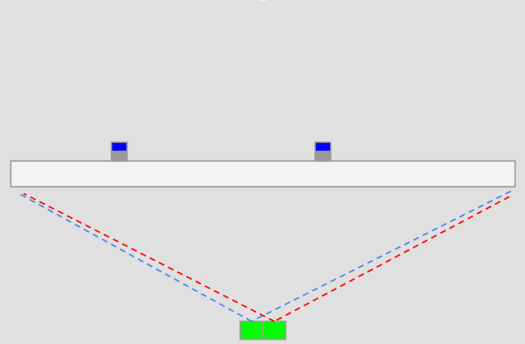
    Heres the idea of this approach: First, we have a whole bunch of light sensors around the perimeter of the TV. These sensors are facing inwards across the screen and have a fixed field of view. Each miniature has a base which also has infrared light emitters, facing outwards toward the edges of the screen (and therefore the light sensors). By flashing a unique code, the sensors on the perimeter of the TV can identify the existence of that mini.

    The trick here is that since those sensors have a fixed field of view, they can only see some amount of the screen. By comparing which sensors could and could not see the flashing mini, we can create bounds on where the mini could possibly be on the screen. Hopefully, those bounds are small enough that we can say we successfully located a mini and use that to update the VTT.

    Side view

    Following is my attempt at creating a walkthrough of how this system might triangulate a mini:

    Slide 1

    Top view of system. The mini base is emitting light sideways, to be received by sensors along the perimeter.

    Slide 2

    By considering the field of view of one of the sensors which CANNOT see the mini, we get some initial bounds of where it might be.

    Slide 3

    As we consider more sensors, the bounds of possible locations gets smaller.

    Slide 4

    Sensors which CAN see the mini are also useful to provide tighter bounds.

    Slide 5

    By considering all these sensors, we know the mini must be within the green region. Considering more sensors may tighten these bounds.

    previous arrow
    next arrow

    Advantages

    • Inline to TV: You could build this into a frame with the TV so that the perimeter sensors are protected and the system is essentially one piece.
    • Calibrate once: Once mounted, framed, and calibrated, the system should not go out of calibration.

    Disadvantages

    • Requires a custom frame: The frame would be to be sized to the TV. For a one-off project this might be fine, but if it were to be commercialized there would need to be multiple frame options available.
    • More accuracy == more $$$: To increase the accuracy of the system we need to increase the number of sensors in the frame, which increases the cost.

    Current Approach

    The above approach was getting complicated fast and I was beginning to become worried about accuracy and cost. While I am unsure if I will attempt to sell whatever I come up with, I also want to keep that as an option. The more hardware I require someone to set up the less likely they would ever consider using it, especially if it ends up kind of expensive.

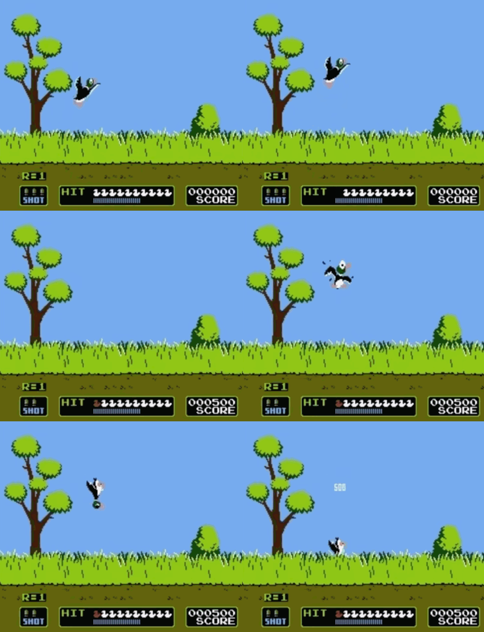
    While mulling over other ways to solve this problem, I happened to remember the old NES game “Duck Hunt” and the trick they used to detect if you successfully shot a duck.

    Slowed down to make it more obvious

    If you watch real closely, you’ll see that very briefly the screen goes black and the location of the duck is a bright white square. The “gun” for Duck Hunt is mostly just a tube with a photoresistor at the back. This forces the photoresistor to only have a very small field of view. When you pull the trigger, the screen is switched to that black screen and each duck is replaced by a white square in sequence. With that limited field of view, it can only see a small region of the screen. If a bright spot is detected you must be pointing at a duck and it is “shot”.

    Why is this useful for tracking minis? The lesson to be learned from Duck Hunt is the screen is able to convey location information. If the mini is able to read that location information from the screen and then pass it back via some side channel (since the screen can only “output” information, it can’t read from the mini), we would have a way of locating the mini on the screen.

    Because checking for one valid location at a time would take a while (and be very visually distracting), I’m instead going to encode the location information in a series of flashes. The simplest seems to be sending the X and Y coordinates as a series of flashes, encoded in binary.

    The screen before sending information
    The screen sending some of the location information. Lighter regions could be binary “1” and dark regions binary “0”

    In addition, I can send a checksum value, which is nothing more than a few bits sent after the X and Y coordinates which can help indicate if the transmission failed in some way. After the mini receives its location, it will then transmit it back to the computer running the screen via Bluetooth low energy (BTLE). Depending on how many bits are required for the coordinates plus checksum, I’m hoping all the information can be transmitted in “the blink of an eye”, reducing the visual distraction. I’ve implemented some test code which is demonstrated in the following video:

    On the bottom left is a light sensor taped to my screen. When I click on its grid, the window begins transmitting all of the locations. Looking closely, you’ll see that every grid is flashing a bit different. Remember, all locations are being sent simultaneously, not just one. The sensor can then be used to determine which of the locations it saw, which it then passes back to the computer.

    Advantages

    • No Masking: Minis generally cannot “mask” each other. If the mini is on the screen, it can see the locations being transmitted.
    • Unlimited mini tracking: You are only limited by the number of minis you can physically fit on the screen (which should far exceed the number you actually want to use). Each mini does not incur a noticeable increase in processing time for the system.
    • Minimal external hardware: The mini bases are the only special hardware needed, with a target manufacture size of roughly 1 inch (the common size of grid squares and mini bases).

    Disadvantages

    • Complicated: This approach gets complicated fast and introduces problems like keeping the flashing synced with the rate expected by the minis, needing to manage a Bluetooth data channel, and specialized circuitry for the bases.
    • PCB density: We need to cram a lot of functionality into a 1-inch base. That will likely require components too small for me to comfortably hand solder.

    Possible Problems (and Possible Solutions)

    • Screen flashing is a slow/low bitrate transfer scheme
      • My hope is the screen flashing is only needed to give the initial position. Then I can include an inertial measurement unit (IMU) and use it to estimate the new position of a mini when it is moved. After it is moved, I can potentially only flicker a small region (possibly only under the mini) to check that the mini ended up where I estimated.
    • Using the IMU to estimate position could introduce a new problem, what if the TV gets bumped?
      • If we are using the IMU to estimate position relative to the screen, and the screen moves, we need to be aware of that to correct the estimated position. One option might be to have a mini base attached to the screen. That way, when it moves, we know how the screen moved to update our estimates.
    • No way for players to interact with objects on the map
      • We might have doors that the players should be able to open. To handle this, we could use the IMU on the mini base. It could detect simple gestures like “double tap” to indicate “Please open this door next to my location”.
    • No way to get an absolute rotation angle
      • Some other tabletop games might give the players some sort of “flashlight”. It would be cool if we could detect mini rotation to shine it the correct way. Most IMUs will include a gyroscope to measure rotation, but that will only be relative to where we started, not relative to the actual orientation of the screen. To address this, we could actually have two light sensors. Then by using some pattern on the screen (potentially a circle with its brightness as a gradient), convey an absolute rotation to the mini. By periodically updating the gyro with this correction, we could handle mini rotation.

    Conclusion

    If this project seems interesting to you, be sure to keep an eye out for part 2. Sharing it with others and leaving comments will also be helpful in providing direction for this project. If you are interested in the code I’ve been generating while playing with this, check it out at: https://github.com/anichno/tabletop-mini-tracker.
  • USB Switcher

    USB Switcher

    Introduction

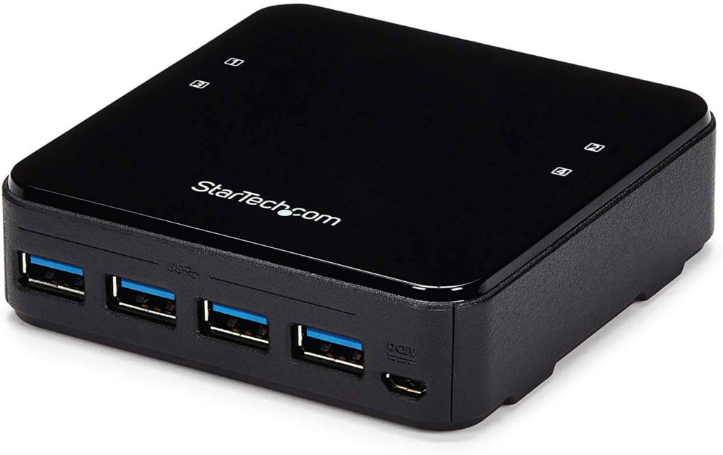
    As a part of my work from home setup, I put together a “poor man’s KVM”. I have 3 computers, 2 monitors, and 1 mouse/keyboard. The first and second computers can share a monitor, and the third gets its own. For switching the display between the 2 computers I just use a simple DisplayPort Switch. To share the keyboard/mouse between the 3 computers, I use a 4 way USB switch.

    DisplayPort Switch
    USB Switch

    Problem

    This setup works reasonably well. Since the DisplayPort connection physically switches between devices, I don’t have to worry about latency at higher framerates. The problem is how you switch the USB Switch. They give you a little button on a 6 ft cable and you press that to move to the next computer. You have to think about which computer you are on and press it the correct number of times. If you want to go back to the previous computer, it results in 3 button presses. Do that enough times and it gets old really quick.

    Solution

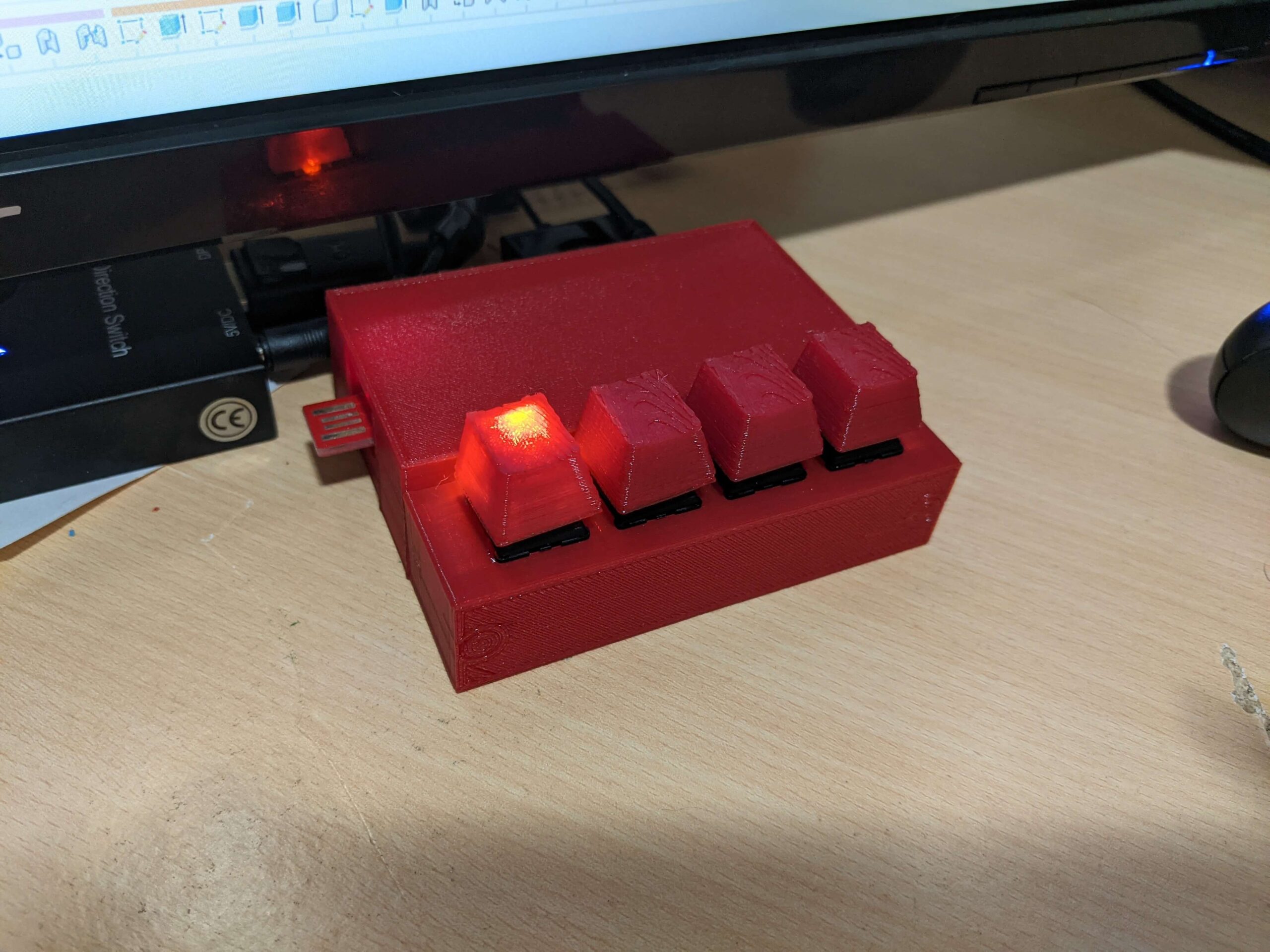
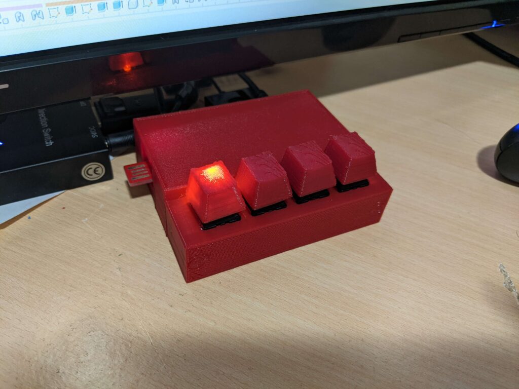
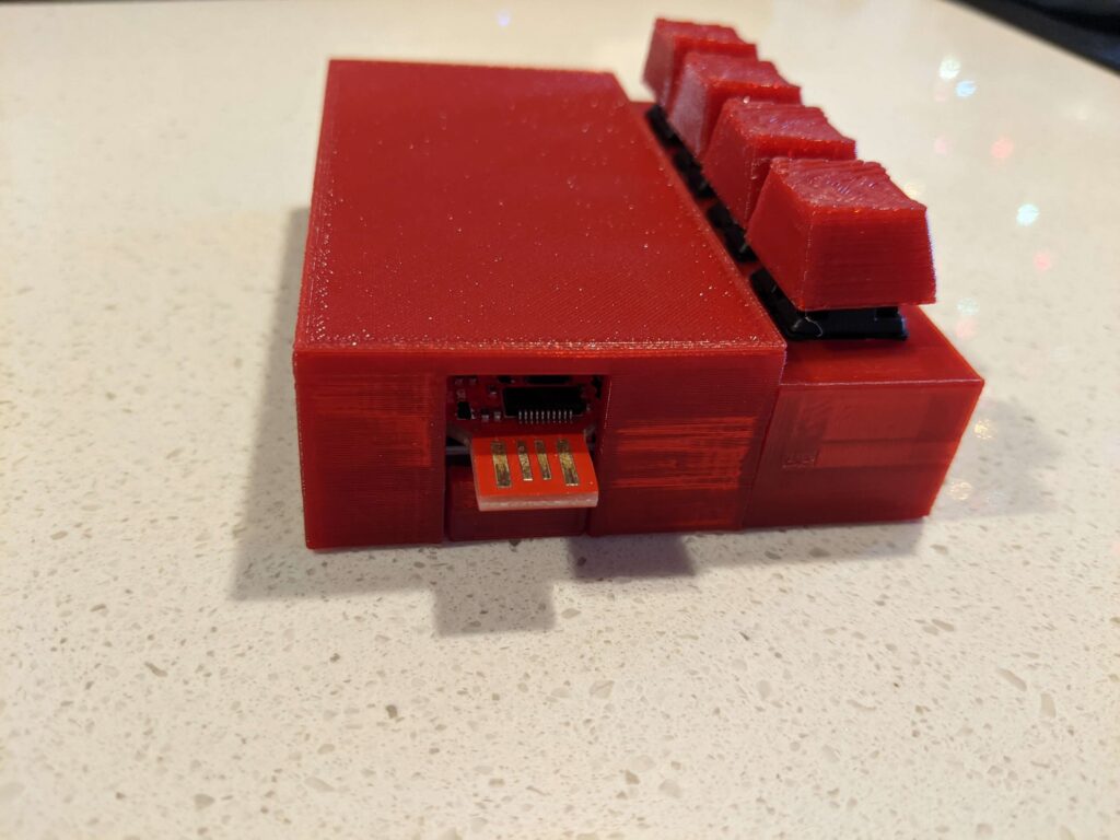
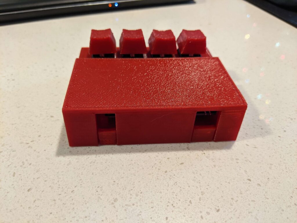
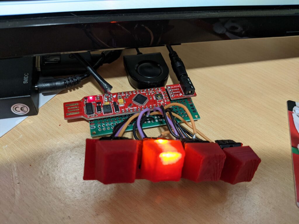
    I built my own switch box! Each physical key on it maps to a specific computer. An LED backlight on the key indicates the currently active computer.

    Bonus Feature

    What happens if the switch box boots up but the first computer isn’t the active one? If you press all 4 buttons together, it switches into a “manual” mode. Just press the first button until computer #1 is active, then press button 4 to go back to regular mode.

    Make your own

    • Code is available on my GitHub
    • STL files for the shell on Thingiverse
    • Parts (estimated, I didn’t create a log of parts while building):
      • 1x 3×7 CM PCB – I used this one
      • 4x cherry keyboard switches
      • 1x SparkFun RedStick (retired, so maybe replace with a small form factor Arduino?) RedStick for reference
      • 1x TRRS 3.5mm Jack Breakout
      • 1x 2.5mm Male to 3.5 Male 4 Conductor Audio Cable
      • 6x M3x8 Bolts
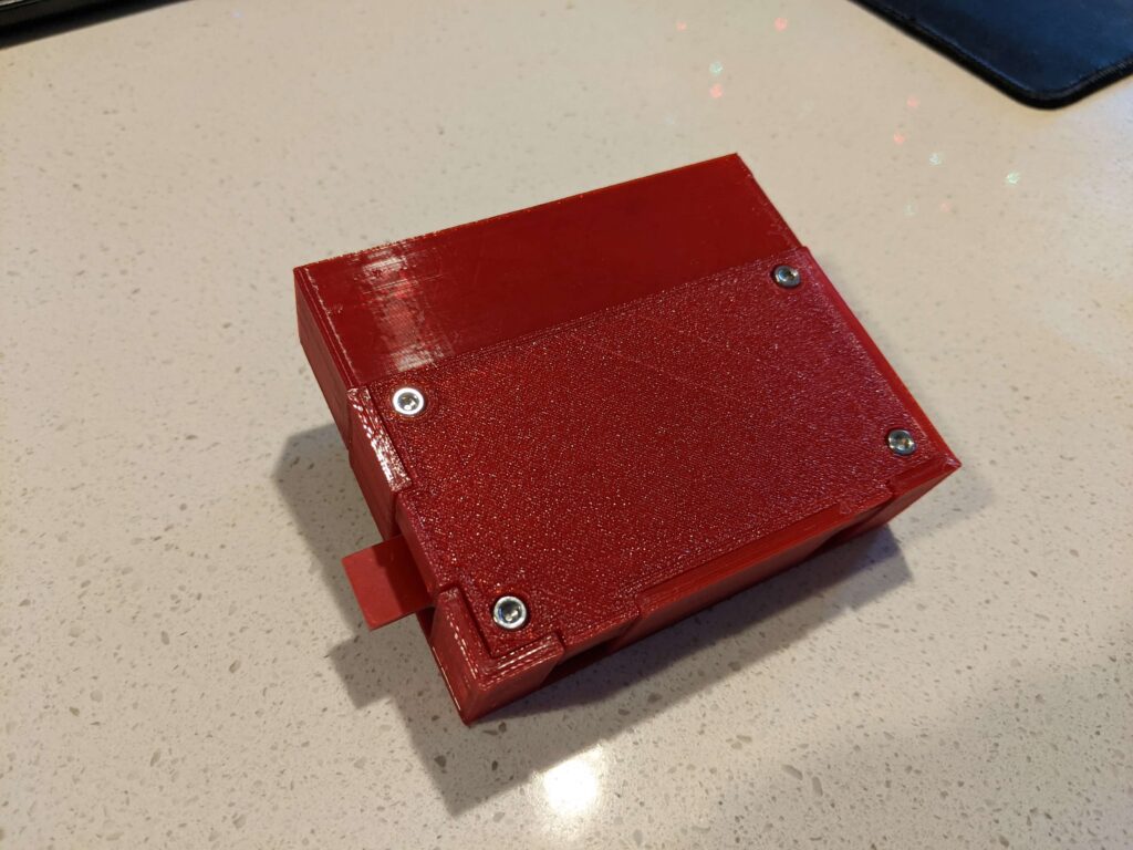
      • 2x M3 heat-set inserts (to hold the front key box to the main shell. If you modify the STL to shrink the hole size that would probably be fine. I just like heat-set inserts) example

    Discussion

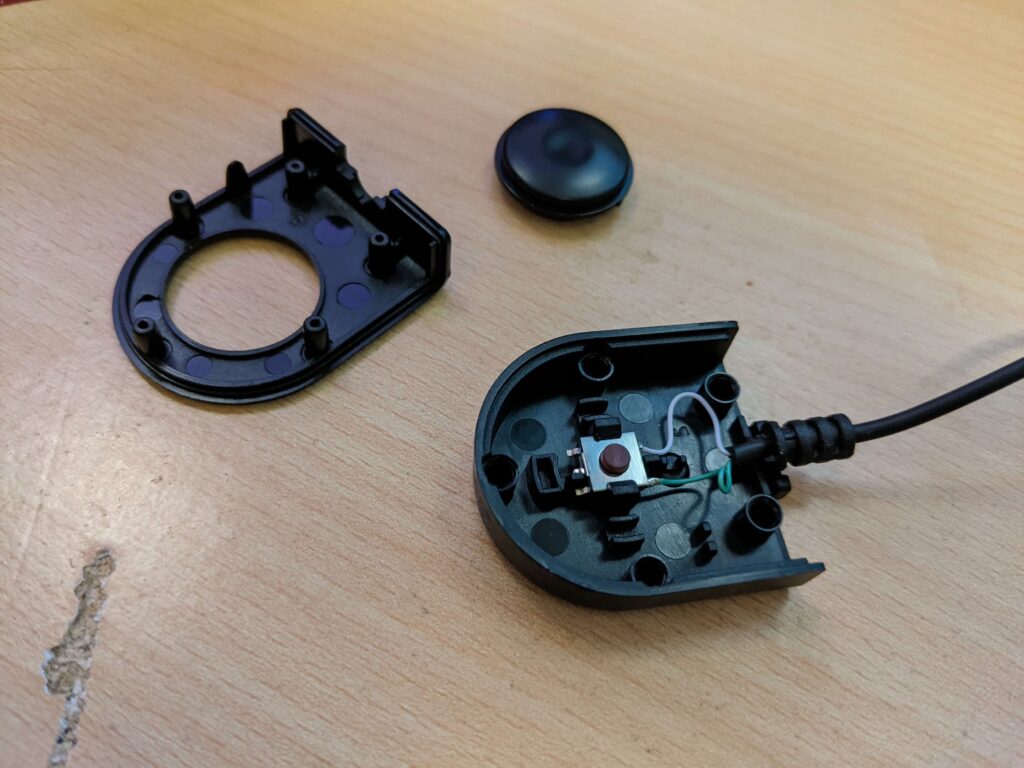
    First I needed to determine how the button worked. It is just a snap-together part, so disassembly is really easy.

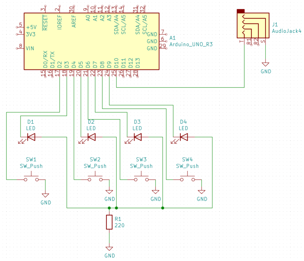
    Looks like it’s just 2 wires. A quick check with a multimeter in continuity mode shows that the tip and the ring of the TRRS connector are connected when you push the button. Using the multimeter to check when plugged into the actual USB Switch Hub shows that the tip is held at 5V and the ring is ground. Easy enough, we just need to hold the tip HIGH until we want to “click” it, during which we will briefly bring it LOW.

    The keyboard keys are easy as well. I just set the Arduino’s pins to INPUT_PULLUP to pull the pins high via an internal resistor. When you press the keyboard key it will connect the pin to ground, bringing it LOW.

    Since I’ll only have at most 2 LEDs on at a time (manual mode), I’m going to cheat and use a single current limiting resistor for all 4 LEDs.

    With the hardware designed, I soldered it together to start playing with it. I did run into a snag here (this is why you make an electrical schematic). I originally used the 220-ohm resistor as the ground for the buttons. This created an issue where if an LED was on, the buttons would never be able to go LOW when pressed (held HIGH by LED). Originally I made a mess in my code which turned off the LEDs to sample the button, then turned them back on. I figured this was just too nasty to allow, so I went ahead and re-soldered the board to make the buttons actually used ground.

    The code is pretty simple. It just tracks which is the currently active computer, checks for button presses, and if a button is pressed it sends the appropriate number of pulses to switch to that computer.

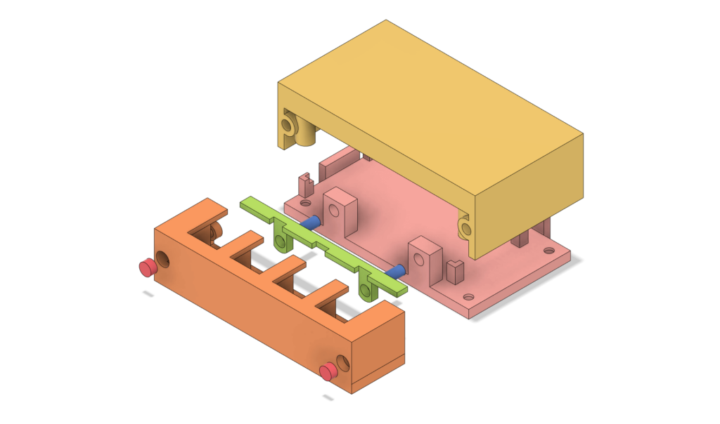
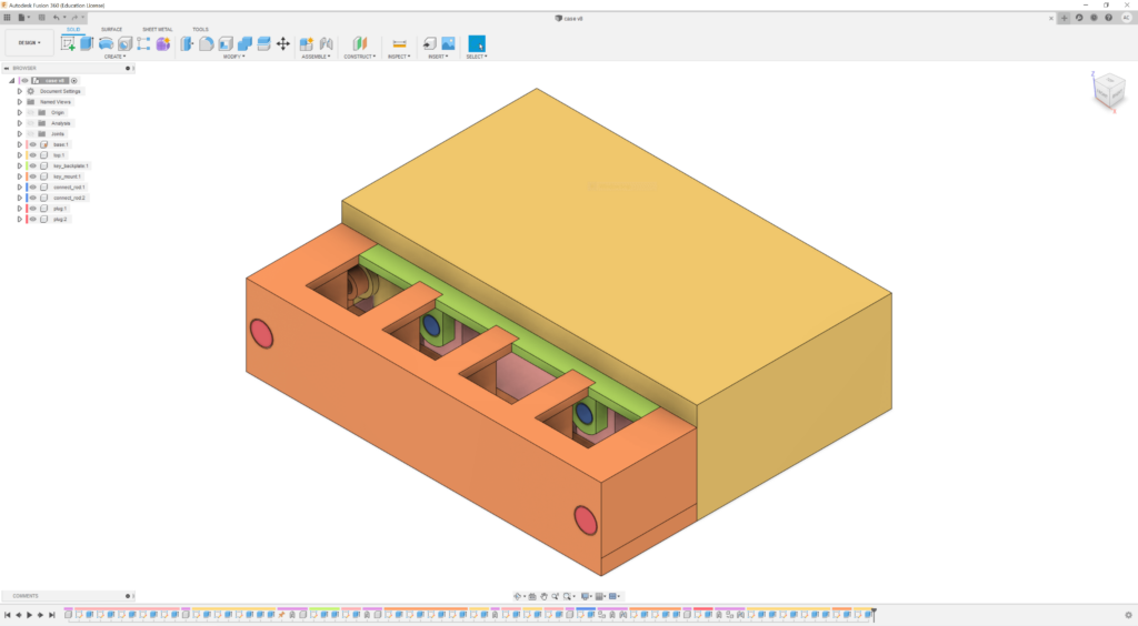
    Once the prototype was working, I just modeled up a case in Fusion 360 and printed it on my 3d printer. I ran into issues printing the thin columns of the key mount (shown in orange below). They were very thin with nothing surrounding them. To fix it I added some ribs connecting the top to bottom.

    Lessons Learned

    • No matter how simple the wiring will be, make an electrical schematic. It will let you better check your work and find hardware bugs much earlier.
    • Tall, thin walls need support. Even a thin rib is much better than nothing.