Contents
Series Introduction
Welcome to my Dungeons and Dragons (D&D) tabletop tracking system project. This has been a complex project I’ve been working on and off for roughly two years. Since I have done presentations in the past, but never written any posts about it, I’ve decided to write these posts as if they had been written when I presented them. Therefore, while I have made many updates and progress over time, these posts will be written with only the knowledge I had then. Hopefully, this will allow you as the reader to follow along as I worked my way through various problems and solutions.
The following post will be written with the project state as of August 2024.
Problem Overview and Background
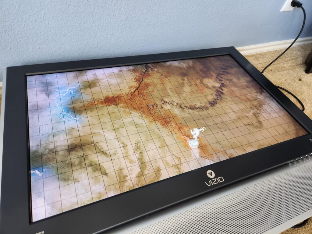
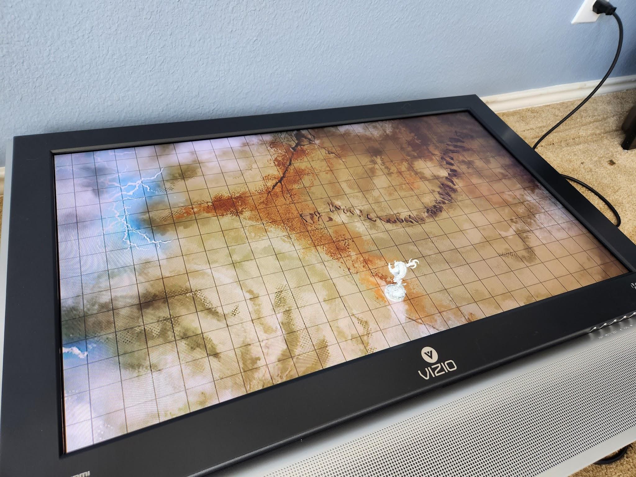
For years I saved a large TV with the intent of building some sort of gaming table. The TV was intended to allow me to do things like run D&D games with dynamic maps and backgrounds. However, I am not a good/competent woodworker and this project never made much progress.
Later, I happened upon a video of someone just putting their TV on an existing table. That is MUCH easier to manage than building a whole table! Instead, at most, I can make myself a nice box for the TV, potentially with a screen protector of some sort. I still haven’t built a box for my TV, but I have run a game where we just put the TV itself on the table.
Instead of building a box for the TV and calling it a day, this spawned the huge project that will be covered by this and future parts. When playing with the dynamic maps using a virtual tabletop system (VTT) called Foundry, I found it super cool that you could have stuff like fog of war and limited fields of view. With that, I could have a full map “technically” on the screen, but until my players explored those areas it would not yet be revealed. Then, as they moved around, they would be able to explore the map.
This is really cool if you are fully virtual or remote, but if playing in person we now have a new issue: how do we tell the VTT where the players are? I don’t want players to have to use something like a mouse, I feel like that breaks immersion. For our in-person game, I let them move their minis around the TV and then I as the game master “dragged” their token in the VTT to the appropriate location on the map. This worked ok but did require overhead on my part. I also needed to enforce a “party token”, so that I wasn’t having to manage multiple people moving around all over the place.
What if players could use their minis (because minis are cool) with the TV-based tabletop system, but the underlying VTT was able to self-update itself with the location of players’ minis? Welcome to my project for the past two years…
Prior Art
I am not the first person to try to solve this problem. There are several really cool and creative solutions already out there, but of course, they weren’t good fits because of <insert arbitrary reason here>. Before getting into the approaches I’ve taken, I think it’s worthwhile to discuss what has come before, what is good about them, and what disadvantages I saw with them.
Overhead IR Camera
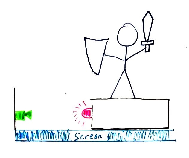
This is probably the simplest and most effective technique to solve this problem. In general, it works like this (with an MS Paint quality visual aid).
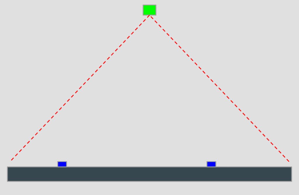
An infrared (IR) camera is placed somewhere above the surface, such as the ceiling. For each mini you wish to track, you put them on some sort of base which is capable of emitting an infrared code. Those codes are unique to each mini, so when the camera sees them, it can then know which mini is where on the physical screen. Using that positional data from the camera, you can update the VTT with the location of that person’s mini.
Advantages
- Simplicity: This system is relatively simple to implement. The mini bases do not need to be particularly smart, only enough to know a globally unique identifier and be able to emit that. Most cameras are sensitive to infrared light, so at worst you just need to remove the IR filter. The system does need to be calibrated, such that positions reported by the camera are calibrated against the physical location of the mini on the screen.
- No Masking: Minis generally cannot “mask” each other, which will be shown to be a bigger issue in other approaches. Basically, if the minis are on the same plane of the screen, none can hide another from the view of the camera.
- Unlimited mini tracking: You are only limited by the number of minis you can physically fit on the screen (which should far exceed the number you actually want to use). Each mini does not incur a noticeable increase in processing time for the system.
Disadvantages
- Requires a camera overhead: The camera must be mounted such that it can see the entire screen with its field of view. This can either be on some sort of boom or ceiling mounted.
- Calibration on each setup: Every time the screen is set up, a calibration routine is needed to make sure the camera’s location is known relative to the screen for tracking.
- Hands can mask minis: Hands and arms passing over the TV can hide minis from the view of the camera.
Example
This solution actually has a commercial product you can purchase and set up. It’s called “Material Plane” and can be found at: https://www.materialfoundry.nl/. It also has a corresponding Foundry VTT module to run it.
If this whole project sounds really cool to you and you want to set it up right now, you should probably just go buy that one.
IR Touch Frames
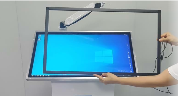
This is another relatively simple approach. It is possible to make a standard TV “touch” capable by attaching an IR touch frame to it (examples: https://www.amazon.com/ir-touch-frame/s?k=ir+touch+frame). This approach works by using that touch information to track the lifting and placing of minis on the screen. As they are picked up, that point of “touch” is removed, and when placed a new “touch” point can be tracked.
Advantages
- Easy touch functionality: If your VTT map includes interactable objects such as doors, you can easily let players interact with them with a simple touch.
- Inline with TV: Since the frame is just mounted to the front of the TV, you could easily build it into a nice frame with the TV.
- Calibrate once: Once mounted and calibrated, the system should not go out of calibration.
Disadvantages
- Minis can mask each other: The frame works by projecting IR beams across the screen. This creates “dead zones” around things touching the screen since they create shadows.
- Single mini tracking: This system works well if you only want to track one mini (such as a “party” token), but has issues with more than one mini. An example: you and your friend both pick up your minis, then place them again. With this, the system has no way of tracking which mini is which. The minis never had a way of identifying themselves, so instead at some point in the past we told the system that “touch point 1 is mini A”. Future tracking relies on assumptions of that point leaving and coming back as the same mini.
Under Table Projector/Camera
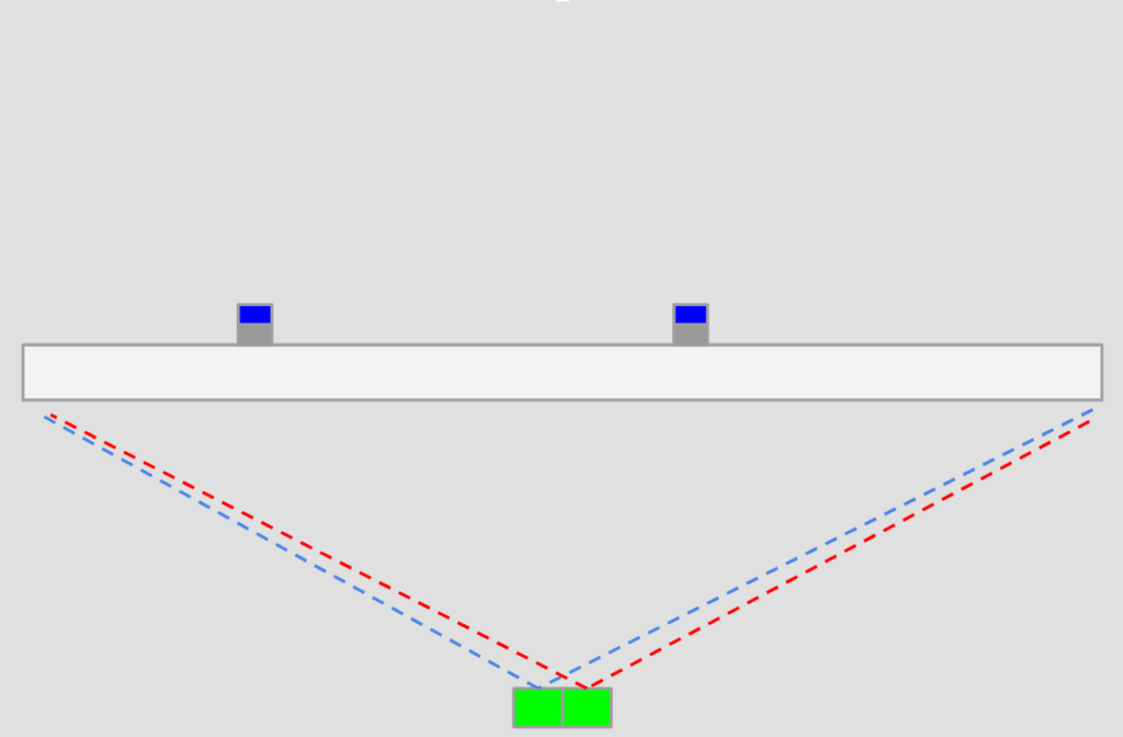
I thought this approach was quite clever. Sadly, after I saw it I failed to save the link to it to be able to source it later. Instead of using a standard TV screen, it used a projector hidden in a table under the screen, facing up. It could then project an image onto the screen from behind. Since the screen allowed light through (you could see the image after all), the researchers put QR codes on the bottom of objects they wanted to track. By putting a camera next to the projector, the system could look up at the screen and read the QR codes, giving it the ability to track the locations of objects on the screen.
Advantages
- No masking: If a mini was on the surface of the screen, it could be seen. No mini could “hide” another from the camera.
- Simple software implementation: Make each QR code unique, then associate that code to a mini. Simply reading the camera and looking for the locations of each QR code gives you the location of the mini with which to update the VTT.
- Unlimited mini tracking: You are only limited by the number of minis you can physically fit on the screen.
Disadvantages
- Specialized construction: While a cool idea, this requires building the entire physical system yourself. To my knowledge, there is no commercial product for sale that implements this.
- Not portable: As described, this system is large enough that it would likely be placed and never moved.
My First Approach
I spent a lot of time on this first approach before ultimately abandoning it. I even got as far as having printed circuit boards (PCBs) made!
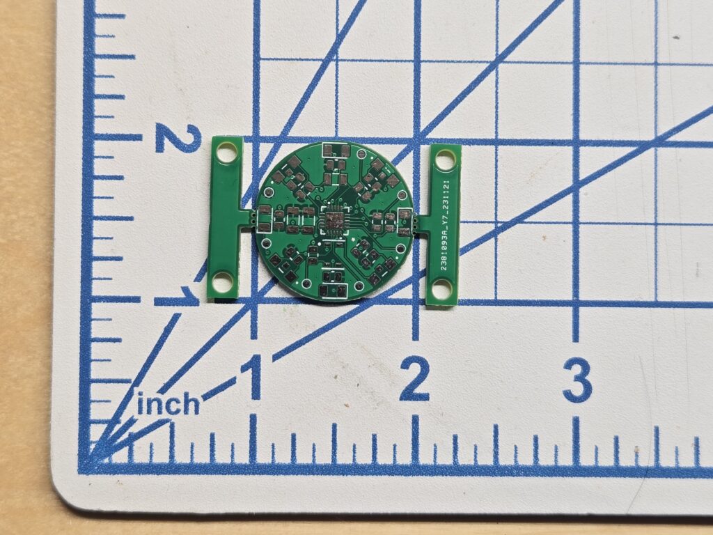
Heres the idea of this approach: First, we have a whole bunch of light sensors around the perimeter of the TV. These sensors are facing inwards across the screen and have a fixed field of view. Each miniature has a base which also has infrared light emitters, facing outwards toward the edges of the screen (and therefore the light sensors). By flashing a unique code, the sensors on the perimeter of the TV can identify the existence of that mini.
The trick here is that since those sensors have a fixed field of view, they can only see some amount of the screen. By comparing which sensors could and could not see the flashing mini, we can create bounds on where the mini could possibly be on the screen. Hopefully, those bounds are small enough that we can say we successfully located a mini and use that to update the VTT.
Following is my attempt at creating a walkthrough of how this system might triangulate a mini:
Advantages
- Inline to TV: You could build this into a frame with the TV so that the perimeter sensors are protected and the system is essentially one piece.
- Calibrate once: Once mounted, framed, and calibrated, the system should not go out of calibration.
Disadvantages
- Requires a custom frame: The frame would be to be sized to the TV. For a one-off project this might be fine, but if it were to be commercialized there would need to be multiple frame options available.
- More accuracy == more $$$: To increase the accuracy of the system we need to increase the number of sensors in the frame, which increases the cost.
Current Approach
The above approach was getting complicated fast and I was beginning to become worried about accuracy and cost. While I am unsure if I will attempt to sell whatever I come up with, I also want to keep that as an option. The more hardware I require someone to set up the less likely they would ever consider using it, especially if it ends up kind of expensive.
While mulling over other ways to solve this problem, I happened to remember the old NES game “Duck Hunt” and the trick they used to detect if you successfully shot a duck.
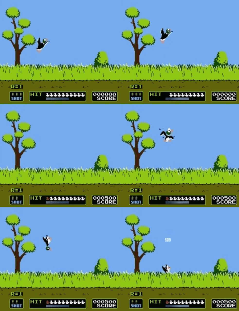
If you watch real closely, you’ll see that very briefly the screen goes black and the location of the duck is a bright white square. The “gun” for Duck Hunt is mostly just a tube with a photoresistor at the back. This forces the photoresistor to only have a very small field of view. When you pull the trigger, the screen is switched to that black screen and each duck is replaced by a white square in sequence. With that limited field of view, it can only see a small region of the screen. If a bright spot is detected you must be pointing at a duck and it is “shot”.
Why is this useful for tracking minis? The lesson to be learned from Duck Hunt is the screen is able to convey location information. If the mini is able to read that location information from the screen and then pass it back via some side channel (since the screen can only “output” information, it can’t read from the mini), we would have a way of locating the mini on the screen.
Because checking for one valid location at a time would take a while (and be very visually distracting), I’m instead going to encode the location information in a series of flashes. The simplest seems to be sending the X and Y coordinates as a series of flashes, encoded in binary.
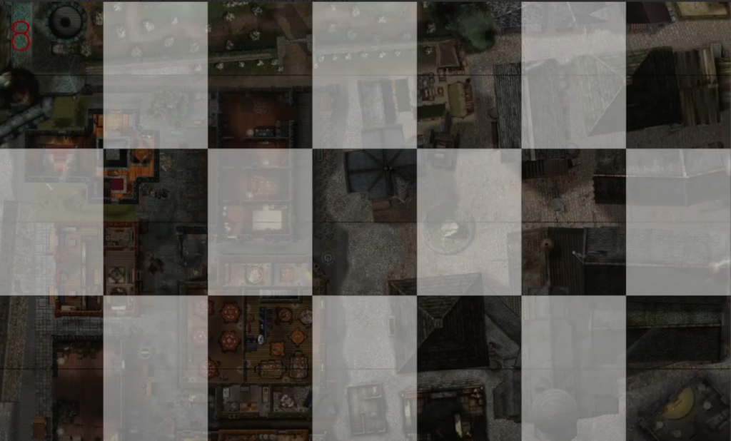
In addition, I can send a checksum value, which is nothing more than a few bits sent after the X and Y coordinates which can help indicate if the transmission failed in some way. After the mini receives its location, it will then transmit it back to the computer running the screen via Bluetooth low energy (BTLE). Depending on how many bits are required for the coordinates plus checksum, I’m hoping all the information can be transmitted in “the blink of an eye”, reducing the visual distraction. I’ve implemented some test code which is demonstrated in the following video:
On the bottom left is a light sensor taped to my screen. When I click on its grid, the window begins transmitting all of the locations. Looking closely, you’ll see that every grid is flashing a bit different. Remember, all locations are being sent simultaneously, not just one. The sensor can then be used to determine which of the locations it saw, which it then passes back to the computer.
Advantages
- No Masking: Minis generally cannot “mask” each other. If the mini is on the screen, it can see the locations being transmitted.
- Unlimited mini tracking: You are only limited by the number of minis you can physically fit on the screen (which should far exceed the number you actually want to use). Each mini does not incur a noticeable increase in processing time for the system.
- Minimal external hardware: The mini bases are the only special hardware needed, with a target manufacture size of roughly 1 inch (the common size of grid squares and mini bases).
Disadvantages
- Complicated: This approach gets complicated fast and introduces problems like keeping the flashing synced with the rate expected by the minis, needing to manage a Bluetooth data channel, and specialized circuitry for the bases.
- PCB density: We need to cram a lot of functionality into a 1-inch base. That will likely require components too small for me to comfortably hand solder.
Possible Problems (and Possible Solutions)
- Screen flashing is a slow/low bitrate transfer scheme
- My hope is the screen flashing is only needed to give the initial position. Then I can include an inertial measurement unit (IMU) and use it to estimate the new position of a mini when it is moved. After it is moved, I can potentially only flicker a small region (possibly only under the mini) to check that the mini ended up where I estimated.
- Using the IMU to estimate position could introduce a new problem, what if the TV gets bumped?
- If we are using the IMU to estimate position relative to the screen, and the screen moves, we need to be aware of that to correct the estimated position. One option might be to have a mini base attached to the screen. That way, when it moves, we know how the screen moved to update our estimates.
- No way for players to interact with objects on the map
- We might have doors that the players should be able to open. To handle this, we could use the IMU on the mini base. It could detect simple gestures like “double tap” to indicate “Please open this door next to my location”.
- No way to get an absolute rotation angle
- Some other tabletop games might give the players some sort of “flashlight”. It would be cool if we could detect mini rotation to shine it the correct way. Most IMUs will include a gyroscope to measure rotation, but that will only be relative to where we started, not relative to the actual orientation of the screen. To address this, we could actually have two light sensors. Then by using some pattern on the screen (potentially a circle with its brightness as a gradient), convey an absolute rotation to the mini. By periodically updating the gyro with this correction, we could handle mini rotation.
Conclusion
If this project seems interesting to you, be sure to keep an eye out for part 2. Sharing it with others and leaving comments will also be helpful in providing direction for this project. If you are interested in the code I’ve been generating while playing with this, check it out at: https://github.com/anichno/tabletop-mini-tracker.


Leave a Reply